Home » Without Label » 3 Way Switch Wiring / 3 Way Switch Wiring Diagram With Dimmer - Wiring Diagram ... - To connect the switches, simply score the wire with your wire stripper and push the insulation to expose about 3/4 in.
3 Way Switch Wiring / 3 Way Switch Wiring Diagram With Dimmer - Wiring Diagram ... - To connect the switches, simply score the wire with your wire stripper and push the insulation to expose about 3/4 in.
3 Way Switch Wiring / 3 Way Switch Wiring Diagram With Dimmer - Wiring Diagram ... - To connect the switches, simply score the wire with your wire stripper and push the insulation to expose about 3/4 in.. The white wire from the power panel would help directly on to the light fixture. The white wire becomes the energized switch leg, as indicated by using black or red electrical tape. Pick the diagram that is most like the scenario you are in and see if you can wire your switch! Of the three bilge pump switches the only one that's not extremely simple is the backlit auto/manual bilge pump switch. Please leave a comment and a like if this video helped you.
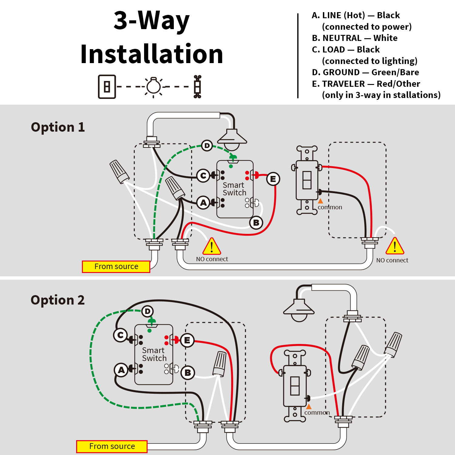
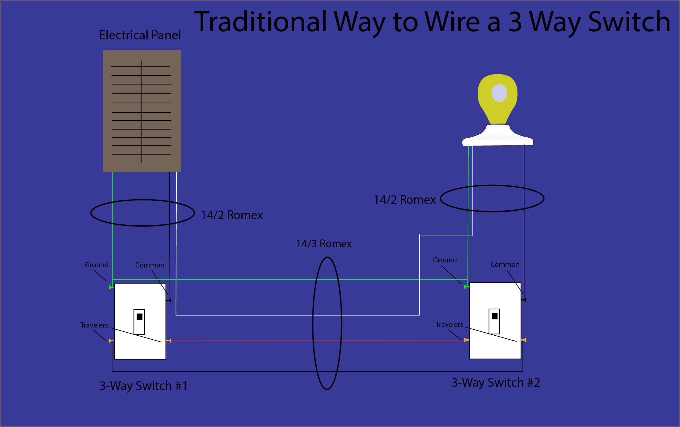
2 wire cable runs from the light to the first switch, and then 3 wire is run between all the switches. Please leave a comment and a like if this video helped you. Take a closer look at a 3 way switch wiring diagram. In this configuration, the power enters the first switch, and the light fixture is placed after the second switch. Red wire (traveler or switch wire).
3 Way Switch Wiring - EVA LOGIK from nie-tech.com Wiring diagram 3 way switch with light at the end. The white wire from the power panel would help directly on to the light fixture. The black and red wires between sw1 and sw2 are connected to the traveler terminals. The white wire becomes the energized switch leg, as indicated by using black or red electrical tape. These wires connect to the brass screws on the switch. The 3 wire cable enters through the top of the first switch box. It is really simple to attract a wiring diagram; When wiring a 3 way with power in the light do you need to take a little different step.
The white wire of the cable going to the switch is attached to the black line in the fixture box using a wire nut.
When wiring a 3 way with power in the light do you need to take a little different step. The white wire becomes the energized switch leg, as indicated by using black or red electrical tape. Power from the panel with 14/2 would come into the light box first or the octagon. 2 wire cable runs from the light to the first switch, and then 3 wire is run between all the switches. The white wire of the cable going to the switch is attached to the black line in the fixture box using a wire nut. It is really simple to attract a wiring diagram; 3 way switch wiring diagram with power feed via light : Please leave a comment and a like if this video helped you. It doesn't make any difference how you connect them at each switch. With these diagrams below it will take the guess work out of wiring. Pick the diagram that is most like the scenario you are in and see if you can wire your switch! The 3 wire cable enters through the top of the first switch box. These wires connect to the brass screws on the switch.
The white wire of the cable going to the switch is attached to the black line in the fixture box using a wire nut. The black and red wires between sw1 and sw2 are connected to the traveler terminals. It's a foolproof way for a proper. (learn more about how our awesome backlit switches work here) even that one is still pretty straightforward though, here are some diagrams that show the single jumper required on the back of the switch. With these diagrams below it will take the guess work out of wiring.
How to wire a 3 way switch - Smart Home Mastery from www.smarthomemastery.com C) the wires from the power source go from switch to switch, and then go to the light. With these diagrams below it will take the guess work out of wiring. 2 wire cable runs from the light to the first switch, and then 3 wire is run between all the switches. The white wire from the power panel would help directly on to the light fixture. The wiring method will depend on whether your power goes to the switch first or the light first. Red wire (traveler or switch wire). It is really simple to attract a wiring diagram; The wiring diagram is normally made use of in electrical design to plan the positioning of electric circuits.
In this diagram, the electrical source is at the first switch and the light is located at the end of the circuit.
(learn more about how our awesome backlit switches work here) even that one is still pretty straightforward though, here are some diagrams that show the single jumper required on the back of the switch. In this diagram, the electrical source is at the first switch and the light is located at the end of the circuit. The white wire becomes the energized switch leg, as indicated by using black or red electrical tape. Wire the 3 way with power in the switch. The wiring diagram is normally made use of in electrical design to plan the positioning of electric circuits. With conventional wiring, the common wire from one switch connects to line, the common wire from the other switch connects to the load. 3 way switch wiring diagram. It doesn't make any difference how you connect them at each switch. The 3 wire cable enters through the top of the first switch box. Take a closer look at a 3 way switch wiring diagram. It is really simple to attract a wiring diagram; This 3 way switch wiring diagram shows how to wire the switches and the light when the power is coming to the light switch. You simply need to have a good comprehension on various kinds of wiring and also their functions.
You simply need to have a good comprehension on various kinds of wiring and also their functions. It doesn't make any difference how you connect them at each switch. 3 way switch wiring diagram. With conventional wiring, the common wire from one switch connects to line, the common wire from the other switch connects to the load. In this case, electricity flows through the ceiling box from the first switch to the second switch.
3-way switch with power feed via the light | How to wire a ... from www.howtowirealightswitch.com The wiring method will depend on whether your power goes to the switch first or the light first. The white wire from the power panel would help directly on to the light fixture. Take a closer look at a 3 way switch wiring diagram. Wire the 3 way with power in the switch. These wires connect to the brass screws on the switch. It is really simple to attract a wiring diagram; C) the wires from the power source go from switch to switch, and then go to the light. Please leave a comment and a like if this video helped you.
With these diagrams below it will take the guess work out of wiring.
You simply need to have a good comprehension on various kinds of wiring and also their functions. (learn more about how our awesome backlit switches work here) even that one is still pretty straightforward though, here are some diagrams that show the single jumper required on the back of the switch. Red wire (traveler or switch wire). Pick the diagram that is most like the scenario you are in and see if you can wire your switch! These wires connect to the brass screws on the switch. 2 wire cable runs from the light to the first switch, and then 3 wire is run between all the switches. In this diagram, the electrical source is at the first switch and the light is located at the end of the circuit. It's a foolproof way for a proper. Video includes the bonus addition of addi. This 3 way switch wiring diagram shows how to wire the switches and the light when the power is coming to the light switch. The white wire of the cable going to the switch is attached to the black line in the fixture box using a wire nut. When wiring a 3 way with power in the light do you need to take a little different step. The white wire becomes the energized switch leg, as indicated by using black or red electrical tape.